Centrifugal Clutch Design & Build
Project Overview
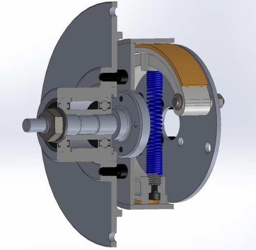
This group project involved designing and manufacturing a centrifugal clutch to transfer torque from a motor to a generator at specific rotational speeds. The design features two internally expanding shoes separated by a helical spring, chosen for manufacturability and efficient torque transfer.
Design Challenge
The clutch needed to automatically engage at 1200 rpm and transfer at least 0.5 Nm of torque to the generator at 2300 rpm, while fitting within strict dimensional constraints (less than 44mm between plates). The design required balancing centrifugal force, spring tension, and friction characteristics.
Design Solution
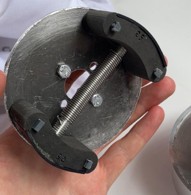
The clutch uses a two-shoe parallel configuration with a single Lee spring (LE 045D 09 S) between them. At 1200 rpm, centrifugal force equals spring force, allowing the shoes to slide outward by 1mm along four restraining pins. The permali-lined shoes then contact the aluminium drum, transferring torque through friction.
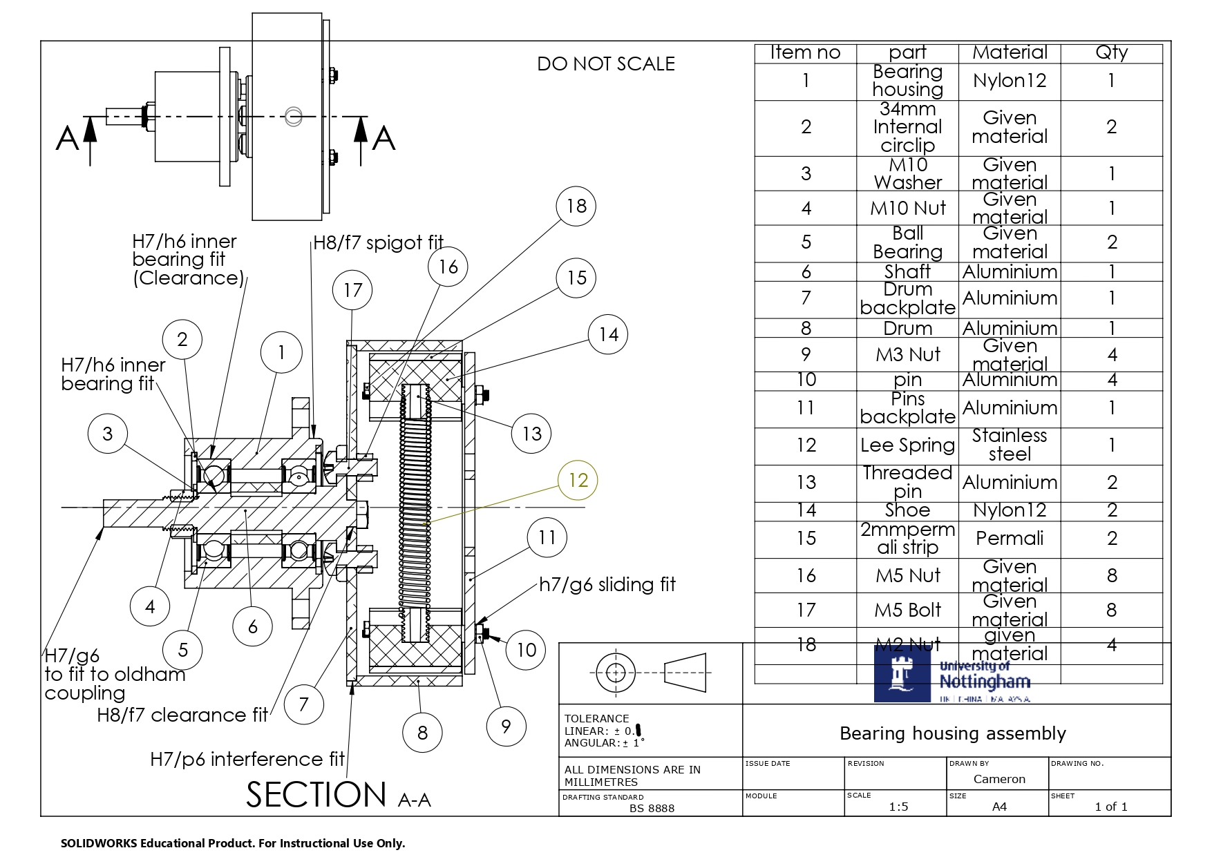
Key Components
- Shoes: 3D printed from Nylon 12 with 2mm permali strips for friction (coefficient 0.25 against aluminium)
- Drum: Aluminium 6063-T6 with H7/p6 interference fit to drum backplate
- Shaft: Aluminium with SKF 6201-2Z bearings separated by 15mm spacer
- Spring: Cut from 63.5mm to 54.2mm, extended to 56.6mm operational length
Calculations & Analysis
Extensive calculations validated the design:
- Centrifugal force calculations: Fcf = m × k × ω² (where k = radius of gyration = 37.96mm)
- Spring force matching at 1200 rpm ensuring smooth engagement
- Torque calculation: T = μr × N × (Fcf - Fs) = 0.966 Nm at 2300 rpm
- H7/p6 interference fit analysis proving minimum torque capability of 0.923 Nm
- Shaft minimum diameter of 7mm based on yield stress calculations
- Bearing load analysis confirming 59.2N << 7280N rated capacity
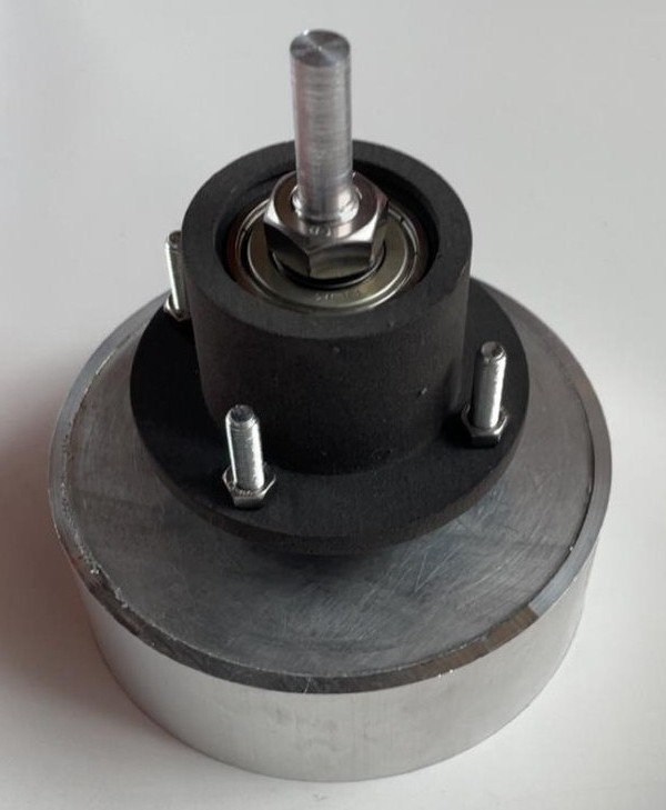
Manufacturing Approach
The design prioritized manufacturability through strategic use of 3D printing and conventional machining. Nylon 12 shoes were 3D printed to achieve precise curved geometry and low mass, while aluminium components were machined on lathes and mills in the university workshop.
Project Photos / Further Design Details:
Skills Developed
- Mechanical design for rotating systems
- Centrifugal force and spring mechanics calculations
- Interference fit analysis and tolerance specification (H7/p6, H7/g6)
- Material selection for friction applications
- Hybrid manufacturing (3D printing + conventional machining)
- SolidWorks CAD and technical drawing to BS8888
- Group project management and task allocation
Reflection
This project provided valuable experience in designing automatic mechanical systems where multiple forces must balance precisely. The single-spring design simplified calculations and manufacturing compared to multi-spring alternatives, demonstrating how design decisions can improve both analysis and fabrication.
Key challenges included achieving the exact shoe mass through iterative design and selecting spring dimensions to match centrifugal forces at the engagement speed. The use of 3D printing for complex geometries proved essential, as machining the curved shoes from aluminium would have been extremely difficult and time-consuming while potentially being too heavy for the required performance.