Variable Pitch Propeller Concept Design
Project Overview
This individual design project involved developing a complete variable pitch propeller system for marine workboats. The propeller eliminates the need for a reversing gear by varying blade pitch, allowing forward, reverse, and stationary operation with a single control lever. The design integrates hydraulic actuation, custom hub mechanism, and standardized blade forgings.
Design Challenge
The propeller needed to provide reliable pitch control while withstanding shock loads (150% peak torque during fouling), operating in contaminated shallow water, and maintaining oil/water tight integrity. The design had to use existing blade forgings (non-negotiable requirement) and integrate with a 200 bar hydraulic system through rotating concentric oil tubes.
Design Solution
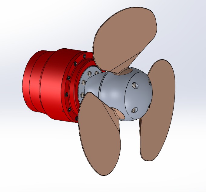
The design uses a hydraulic piston mechanism housed within the propeller hub to control blade pitch. Three blades rotate on bearings within the hub, actuated through a linkage system connected to a central hydraulic piston. Concentric rotating oil tubes (mounted on the 500mm drive shaft) deliver 200 bar hydraulic pressure to control forward/reverse pitch selection.
Key Components
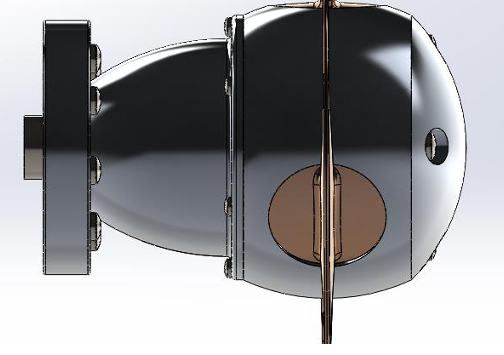
- Hub Assembly: Custom-designed to house pitch mechanism while minimizing diameter for efficiency, integrated with drive shaft flange (defined interface)
- Blade Mechanism: Company-standard forged blades (70% efficiency, non-changeable profile) with machined round bases, mounted on bearings for pitch rotation
- Hydraulic Actuation: Central piston driven by 200 bar hydraulic system through concentric tubes, designed to handle 160 Nm maximum blade root torque
- Bearing & Seals: Rear thrust bearing and cylindrical roller bearing (500mm spacing), designed for contaminated water operation with appropriate sealing to prevent propeller loss
.jpg)
Analysis & Calculations
Comprehensive analysis validated the design:
- Momentum Theory analysis to verify blade suitability and actual vs. ideal propeller area
- Shaft stress analysis for ultimate and fatigue loading (shock torque 150% of peak, 100,000 major cycles)
- Whirling speed calculations for drive shaft and oil tubes (minimum 120% above 1300 rpm operating speed)
- Bolt preload calculations for main flange to prevent fatigue failure and ensure no slippage
- Bearing life calculations for L10 life of 10,000 hours
- Hydraulic system sizing for 160 Nm blade actuation torque at 200 bar pressure
Material Selection
Materials were selected for marine environment durability and manufacturing efficiency. Marine-grade stainless steel and corrosion-resistant alloys were specified for submerged components. Bearing selection prioritized contamination resistance given shallow water operation stirring bottom sediment. All joints specified with appropriate marine sealing to maintain water/oil tight integrity during all operating conditions.
Design Considerations
- Manufacturability: Designed for 5000 units/year production using standard processes (casting, forging, machining), blade forgings already optimized by company
- Safety: Shock load protection (150% peak torque), fouling scenarios addressed, fail-safe design prevents propeller loss
- Integration: Interfaces with existing 2:1 gearbox, 4-cylinder 2L diesel engine, and standard drive shaft arrangement
- Maintenance: Sealing designed to prevent bearing contamination in harsh shallow water conditions
Key Constraints
- Must use company-standard blade forgings (non-negotiable, 70% efficiency)
- Engine limited to 1300 rpm ±2.5% to prevent propeller over-speed inefficiency
- Hydraulic pressure limited to 200 bar (existing system)
- Thrust bearing and roller bearing positions fixed (500mm spacing)
- Drive shaft flange interface predefined
Skills Developed
- Marine propulsion system design
- Hydraulic mechanism design and actuation force calculations
- Momentum Theory application for propeller analysis
- Fatigue and ultimate stress analysis under shock loading
- Whirling speed calculations for rotating shafts
- Bearing selection and L10 life calculations
- Design to strict requirements and non-negotiable constraints
- Material selection for marine corrosive environments
- Technical drawing with fits, tolerances (BS8888), and sectional views
Reflection
This project provided invaluable experience designing a complete mechanical system where multiple requirements must coexist—performance, safety, manufacturing, and cost. The challenge of working with fixed blade geometry (non-negotiable company standard) required optimization of other parameters to achieve target speeds. Understanding how off-design and failure cases (fouling scenarios, shock loads) drive design decisions was crucial.
The most challenging aspect was balancing hub size (minimize for efficiency) against the need to house the pitch mechanism and withstand extreme loads. Momentum Theory analysis revealed the compromise between ideal propeller area and what's achievable with the constrained blade design. The integration of hydraulic actuation through rotating concentric tubes while maintaining oil/water tight sealing required careful attention to standard components (bearings, seals) and their specifications. Future improvements would explore alternative pitch mechanisms to reduce complexity while maintaining reliability in the harsh marine environment.